ASYNCHRONOUS SEQUENTIAL CIRCUIT
1. Agenda
- Introduction
- Block Diagram
- Modes of asynchronous sequential circuit
- Design Flow
- Example Explanation
- Applications
- Advantages
- Disadvantages
2. Introduction
- Asynchronous sequential circuit works without Clock.
- Asynchronous sequential circuit works based on memory concept
- Feedback is present as delay line, and Delay of feedback is not predictable so application of asynchronous sequential circuit is limited.
- Changes in inputs cause changes in output (State changes)
- Asynchronous sequential circuit design is more complicated than synchronous sequential circuit design
- The memory of the asynchronous sequential circuit may include flip-flops or time-delay devices.
3. Block diagram
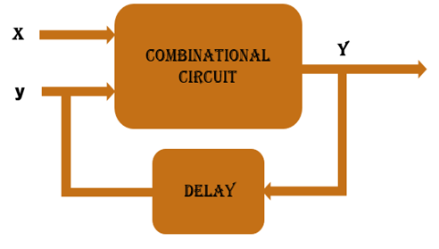
- Here changes in inputs cause changes in output (State changes)
- Here in Block Diagram, Clock is not used but output is directly connected to inputs through some calculated delay (Feedback)
- when Inputs changes then output changes and like this stability is achieved
- When stability is achieved that state is called stable state. Rests of states are unstable states.
4. Modes of asynchronous sequential circuit
- Fundamental Mode
- Only One input can be change at a time after stable state
- This mode is widely used for design.
- Pulse mode: - More than one input can be change at a time after stable state.
5. Design Flow
- Nomenclature
- (a),0 :- Here a is a stable state and 0 is output
- a :- Here a is unstable state and output remain same as previous
- Write word statement from problem statement
- Derive primitive flow table
- Design merger diagram
- Adjacent diagram
- Derive synthesis equation
For more details refer example…..
6. Example
- Problem Statement
- Apply fundamental Mode
- 2 Bit inputs “In1” and “In2”
- 1 bit output “out”
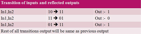
- “out=1” when “In1” changes from “0” to “1” and “In2=1”
- “out=1” when “In2” changes from “0” to “1” and “In1=1”
- “out=0” when “In1” changes from “1” to “0” and “In2=1”
- Problem statement in In/Out form
- Convert problem statement into input and output form it will helpful for designing steps.
- Complex design includes more signals in that case this step is very useful for designing primitive flow table.
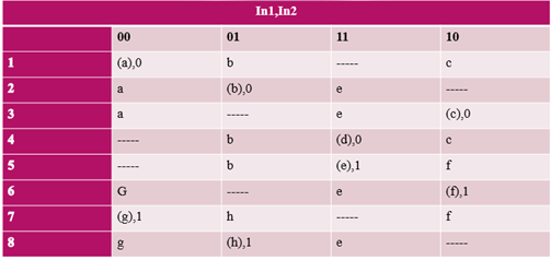
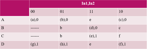
- Primitive flow table
- Primitive Flow table contains stable and unstable states of asynchronous sequential circuit
- All possible combination and its output is listed in the primitive flow table
- First start with stable state "a". So for "00" column state will be (a), 0.
- Fundamental mode is applied here so "00" to "11" transition is not possible so column of "11" will be blank.
- Now transition from "00" to "01" is possible and output will be "0" and state will be unstable because in one row only one stable state is possible.
- Now transition from "00" to "10" is possible and output will be "0" and state will be unstable. Similarly for every transition same rule is applied so primitive table will be like this.
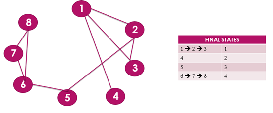
- Merger diagram
- Merger diagram will merge different row by following some rules.
- Stable state and unstable state will be merge and result in to stable state but same state must be there.
- Unstable state and blank(“-“) can be merge into unstable state
- Stable state and blank (“-“) can be merge into stable state.
- Two rows can be merge when all column are follow merge rules.
- In diagram bounded nodes can be merge into one node here bounded nodes are (1,2,3) and (6,7,8)
- For (1,2,3) one node is finalize and it is (1)
- For (6,7,8) one node is finalize and it is (4)
- 4 and 5 is remaining same as primitive table.
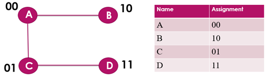
- Adjacent diagram
- Adjacent diagram is useful to assign value to the variables (Here A, B, C and D).
- If small circuit is there then this step can be skipped and in this case random value will be assigned to the variables.
- There are some rules to assign value to the variables.
- Here in the row of "A" and "B" column of "01" "b" stable and unstable state is there so in adjacent diagram "A" and "B" is connected together similarly "A" and "C" is connected together and similarly "C" and "D" is connected together.
- Now to assign value to the variable connected variable should be in Grey coding means difference in bits should not be greater than 1. So, Here "A" and "B" is connected so A=00 B=10 so difference of bit is 1 similarly C=01 and D=11.
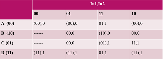
- Revision of merger diagram
- Merger diagram is revised by replacing variables to its values will be like this
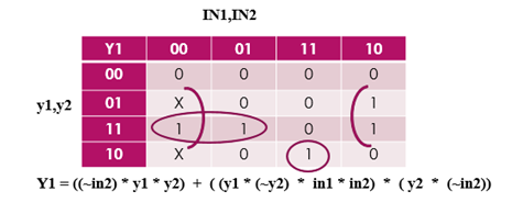
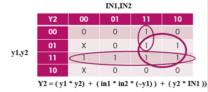
- Synthesis equation for inputs and outputs
- first input synthesis equation is designed by getting First bit from revised merger diagram
- second input synthesis equation is designed by getting second bit from revised merger diagram and similarly
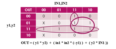
- Output synthesis equation is designed by getting output bit from revised merger diagram.
7. Application
- Asynchronous sequential circuits are useful when circuit system must respond quickly without waiting for clock.
- Asynchronous sequential circuit is important for small circuit which behaves independently and contain few components
8. Advantages
- Robust handling of metastability and higher performance compare to synchronous sequential circuit.
- Faster than Synchronous sequential circuit
- Lower power consumption
- Clock driver can be removed in this case because Clock is not used here so power consumption of clock drivers and controller can be avoided.
- few assumptions are needed in manufacture process
- system speed adapts changes in environment and voltage levels
- Designing of power distribution network is easy here because here leakage current will be less compare to synchronous sequential circuit
9. Disadvantages
- When some encoding is performed then asynchronous circuit requires more area then synchronous circuit and because of the same power consumption may increase
- Area of circuit is increased. No. of Transistors may be double here because of addition of completion detection circuit and design for test circuit
- synchronous sequential circuits are easier to test and debug compare to asynchronous sequential circuit
- Performance of asynchronous sequential circuits may be reducing in architecture which includes complex data paths and feedbacks.
- Race conditions are generated internally and cannot be handling by outside.
