Moving on to a rather interesting subclass of linear codes which are cyclic codes. They were used widely because of 2 reasons, first being the use of shift registers with feedback connections for encoding and syndrome computation purposes; and second, as they had a good algebraic structure, it was possible to find a suitable decoding method for them. This is all possible because of the basic property of cyclic code words, that is if any codeword is shifted cyclically, the result is also a codeword, which means that all codewords can be generated from a single sequence by the processes of shifting and addition.
The process of encoding and decoding for cyclic codes consists of division of the message block by generator polynomial to obtain the remainder which is appended to the message block to produce the codeword and at the receiver end division of the received vector with the generator polynomial to obtain the remainder which is, in turn, the syndrome, but it's all done by modulo 2 arithmetic which can be easily performed with the help of shift register as shown in the figures.
.png)
(1).png)
Now the problem with cyclic codes is that they add too much overhead of redundant information and if there are bandwidth limitations to be met. In some systems, it might be suitable to shorten the above mentioned cyclic codes to fit the purpose of use. A shortened cyclic code implies that the previously mentioned (n,k) cyclic code has been reduced to (n-l,k-l) linear code of 2^(k-l) vectors i.e. it has been shortened by a factor of l. The shortening of the cyclic code points to the upper order bits of the information word considered being zero. The same circuitry as used with cyclic codes can be used for syndrome calculation and decoding of these shortened cyclic code words, taking into account the now extra l digits (ex: by incorporating extra shifts if implementation was done using shift registers)in the new codeword. In many cases, as this might pose an unnecessary overhead, some modifications can be made as well to the circuitry for efficient processing of the shortened cyclic codes.
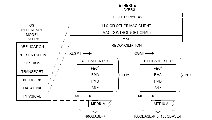
An example of the implementation using the aforementioned shortened cyclic code is the FEC sub-layer for BASE-R PHY's. This FEC uses a (2112,2080) codeword that has been shortened from the (42987,42955) cyclic code and is capable of correcting a 11-bit burst error. A 11-bit burst error can be understood to be a set of consecutive bits where the number of error bits can range from one to eleven. When the entire received vector has been obtained the first and foremost step involved in the FEC on the reception side is the calculation of the syndrome. As mentioned previously a non-zero value indicates the presence of errors in the received vectors in which case the next step involved is finding the received vector bits with the error. While going for burst error detection/correction we try to confine the burst error in a fixed bit window by means of a series of shifts. Post each shift, the changing value of the syndrome is monitored. Let the syndrome value associated with the maximum error, that in this case is a 11bit burst error with an error in each bit is the threshold value 't'. The error can be assumed to have been trapped when the syndrome value being monitored is less than or equal to 't'. By the time the entire received vector has been traversed if this condition is never found to have been satisfied then further steps for negative acknowledgment or retransmission need to be taken as corrupted but uncorrected bits were received.
A major drawback of this type of FEC apart from being limited to maximum 11-bit correction, is that it is built for errors which are confined close together in this particular case a consecutive 11-bit window. This might not always be the case as more often than not the errors tend to be scattered through the received vector.
To overcome some of the limitations Ethernet faced in BASE-R FEC, the high speed Ethernet moved over to Reed Solomon coding schemes for performing Forward Error Correction as it has very high error detection, correction capabilities with a smaller overhead caused by redundant information, and as the benefits increase so does the encoding and decoding complexities which requires strong background in maths. The Reed Solomon codes work on Galois Field arithmetic. A base 2 finite field, is also known as a Galois field. A finite field contains a set of pre-determined elements. The field is constructed using prime number base, as it produces unique value when added, multiplied to any other field elements. This coding scheme follows modulo addition/multiplication. For subtraction and division, we calculate the additive inverse and multiplicative inverse to get the resultant. Galois field is denoted as GF(2^n) where n is the number of elements in the field. The primitive polynomial helps in generating the elements and performing basic arithmetic operations.
(1).png)
The Reed Solomon encoder used in 100G Ethernet is RS(528,514) which operates over the Galois field GF(2^10) where the symbol size is 10 bits, k is 514 symbols and n is 528 symbols. The decoder is capable of correcting [(n-k)/2]=t=7 symbols in the codeword. The encoder divides the Message block by Generator Polynomial using the Galois field arithmetic which produces a parity polynomial and which in turn is appended to the message block to produce the codeword. The decoding part is where there's a lot of work involved. Although the Syndrome is the remainder of the division of the received vector by the generator polynomial, it's a tedious job to do, so we calculate the syndrome by substituting the finite field roots a(n) into the received vector R(X) to produce the syndrome coefficients. which can be further made easy by using the Horner's algorithm. After we compute the Syndrome, we have to figure out the error magnitude and the error location. The error magnitude polynomial determines how many errors are present in the received codeword. These two polynomials are computed by dividing a X^2t polynomial by the syndrome polynomial using Euclidean long division method, where the remainder is error magnitude polynomial and the quotient is the error locator polynomial. These two polynomials are further used by the Chien search algorithm to actually identify the error locations, and finally, Forney algorithm is used to determine the error vector for specific locations.
This is the most advanced encoding scheme used in Ethernet yet to perform forward error correction, in terms of correction capabilities of up to 7 symbols or 70 bits with a very small overhead. However this also has a disadvantage when there are more than 7 symbol errors spread across the codeword, the Chien search algorithm churns out invalid data locations and after this, if correction is attempted, the received vector was further seen to be corrupted. And Truechip has devised a way to circumvent this false correction when no correction is feasible.
In many FEC sub layer of the Ethernet PHY, an option can be provided to bypass the correction phase altogether as the implementer might not want their performance objectives to be hindered with. In such cases, a provision can be made to communicate the presence of the error to the next PHY sub layer in the data flow path.
As seen, the effectiveness of the FEC components is limited by several factors. In the future as the need arises the capabilities of these components can be further enhanced. Currently, the RS-FEC design proposed for the 200G and 400G Ethernet utilizes a (544,514) code increasing the number of parity symbols to 30 from 14, thus increasing the error correction capability from 7 to 15 symbols. Also, newer algorithms that rely on the efficient use of parallelism can reduce the computational load on systems and increase the speed of error detection/correction in high-speed networks.

.png)
